Getting a skin-weighted model from Blender to DS
Author(s): Brom.
Table of Contents
- Introduction
- Blender export settings
- Editing DS-specific material settings
- Exporting the NITRO G3D files
- Common issues
Introduction
Although there are some guides out there for inserting simple animated models using fully-weighted vertices, unfortunately some models require more complex in order to animate them well. Luckily, with this guide, Blender 2.8+, and CTRMap-CE with the CTRMapV plug-in, more complex, skin-weighted models can be used on the DS as well.
For this guide, I will be using Blender 2.93 and the latest versions of CTRMap-CE and CTRMapV. To get the CTRMapV plug-in connected to CTRMap-CE, open CTRMap-CE and select Global plug-in manager, select Install plug-in¹, then select your CTRMapV JAR file. With this, the tools should now be ready.
¹Do note that if the Install plug-in button doesn't open a file dialog, you may need to install 64-bit Oracle Java SE 8. More info can be found in this GitHub Issues log.
Blender export settings
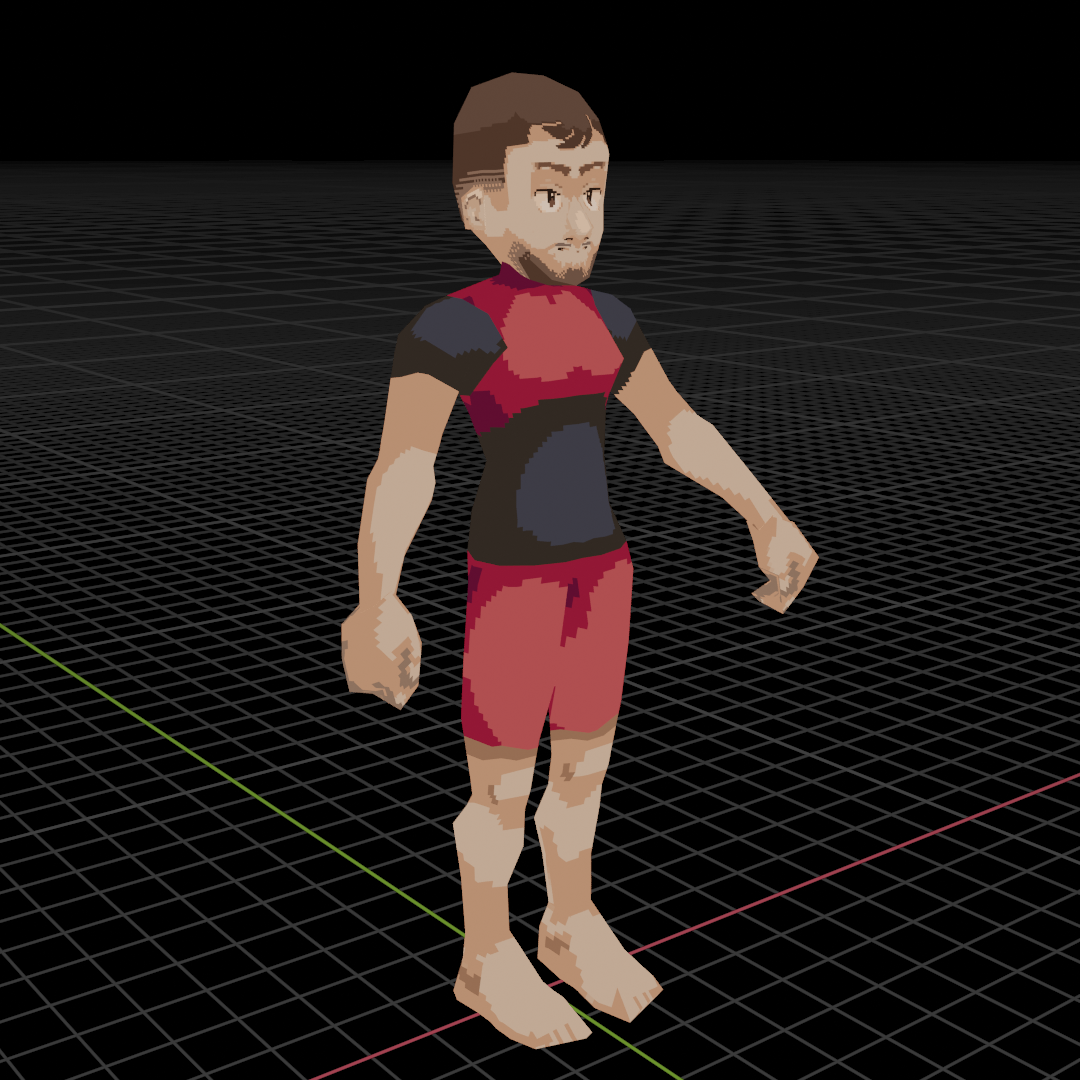 For this tutorial, a sample BLEND file will be provided (602 polys / 509 verts) so that anyone can follow along and check for any issues in their own model.
If you're following along using your own model make sure that:
- Has at most 2048 polygons or 6144 vertices (the smaller of the two)
- There are only triangle or quadrilateral faces on the mesh
- The armature and mesh's scale is
1for every axis or were applied withCTRL + Aif not - The armature and mesh's locations are at the world origin
(0, 0, 0)based on their origin points or were applied withCTRL + Aif not - The armature and mesh's rotations are all 0° or were applied with
CTRL + Aif not - The mesh has the desired armature as its target in the modifier
- All other modifiers are applied to the model
- There is a single root bone for the model hierarchy
- The model's vertex weights are normalized so that each vertex has exactly most 100% (
1.0) influence from its bones - Only the deformation bones have the
Deformproperty in the bone properties selected
After opening your BLEND file and selecting the mesh and armature, we will be exporting our model as a COLLADA (.DAE) file. For each tab the settings should be:
Main
[✓] Selection Only
[ ] Include Children
[ ] Include Armatures (The armature is already selected for export)
[ ] Include Shape Keys (The DS does not support these)

Global Orientation¹
[ ] Apply

Forward Axis X [Y] Z  -X -Y -Z
Up Axis      X  Y [Z] -X -Y -Z

Texture Options
[✓] Copy
¹These orientation settings generally work, but you may need to play around with them some since the exporter seems to just pick whatever direction it wants sometimes.
Geom
[ ] Triangulate (We want to keep our quads generally)

Apply Modifiers [ ]

Transform [ Matrix ]
Arm
[✓] Deform Bones Only²
[ ] Export to SL/OpenSim
²We don't want to export our control bones so that we don't have issues due to having too many bones later. Only the deformation bones will be exported as a result.
Anim
[✓] Include Animations
Key Type [ Samples ]

Sampling Rate [ 1 ]
[ ] Keep Keyframes
[✓] All Keyed Curves³
[✓] Include all Actions
Transform [ Matrix ]
³This may be necessary if the model stays in a static position.
Extra
These don't matter as much, but they will still be shared:
[✓] Use Object Instances
[✓] Use Blender Profile
[ ] Sort by Object name
[ ] Keep Bind Info
[ ] Limit Precision
With these settings, your model should now be ready to put into CTRMap Creative Studio with the next step. Do keep in mind that the orientation may need to be altered depending on what the COLLADA exporter seems to do.
Editing DS-specific material settings
Open CTRMap-CE and select CreativeStudio then the Launch button. From here, at the top, select Import > COLLADA then select your newly generated COLLADA file. This will import the model along with its textures and animation as well. This should show your model within the central viewport. Before we start messing with the materials, if there was a camera exported in your COLLADA file, you may notice a Camera bone added to the model's skeleton after expanding the Skeleton tab. Right click and remove this as this shouldn't be a part of the model's bone hierarchy.
To view the model's materials, expand the Materials folder in the left panel of the model's hierarchy then select a material.
Polygon IDs and what they do
With the DS, polygons are grouped into IDs called Polygon IDs. They get used for a few purposes such as helping with sorting translucent polygons, determining the edge group for edge marking, and determining what edge marking color gets applied to them among other things. For most people, this doesn't need to be touched, but these can be incredibly useful if you want to change these. If you have plans on modifying them, it's best to go into the Shortcuts tab in the right panel and selecting the Setup Nintendo DS shading option underneath Generic shaders with every material first.
Adding outlines
Assuming the scene that the model will be used in has edge marking enabled, edges can be defined by going into the Render State tab and setting the Test reference field in the Stencil operation panel near the bottom. After using the Setup Nintendo DS shading option, the Polygon ID/test reference field should be set to 0 meaning that they all share the same outline or "edge marking" group. If you want two materials to share an edge, make sure they share the same Polygon ID!
A neat trick to add additional outlines is duplicating a material so that you can give it a separate Polygon ID.
Alpha sorting
If two or more translucent polygons share the same Polygon ID, there may be issues determining the sorting order when drawing them. To fix this, make sure that translucent polygons have different Polygon IDs.
Front-face/inverse and no-face culling
Within the Render state tab on the right, at the very bottom there is the Face culling area. By default, it is set to Back face, but if you want both faces to show, set this to Disabled. Alternatively, if you want inverse culling like for an inverse hull outline, set this to Front face.
Adding fog
Assuming that fog is enabled for the entire 3D scene, you can also select if a material will be affected by it or not by going into the Lighting tab on the right inside of the Fog panel and toggling the box on the right.
Ambient, diffuse, and emission color settings
Within the Lighting panel on the right with a material selected, these settings can be changed.
- The ambient light affects the model when in shadow (assuming there are no vertex colors present and it has valid normals).
- The diffuse light is the color multiplied onto the texture when in the light (in addition to getting color from the light itself)
- The emission light brightens the texture regardless of shading. This can be useful if you want a model that gives an unshaded sort of look while still being able to be affected by the color of a light even if you don't want the shadows from it, too.
Setting texture wrap modes
Within the Texturing tab, you can set the behavior for when a UV reaches the edge of a texture in the Mapping section. By default, it will be set to Repeat, but for symmetrical textures, UVing with the Mirrored Repeat option in mind can be helpful to save space with larger textures.
Exporting the NITRO G3D files
Exporting the NSBMD
Once you are done with your changes, right click on the model you want from the Models folder on the left panel and set the export type to Nitro System Binary Model (*.nsbmd). Upon doing that, a dialog will pop up with export options. The following settings should be used:
Included resources
(・)Models and textures
      [ ] Omit unused textures¹
( )Models only
( )Textures only (NSBTX)

Additional options
[ ] Create polygon strips
      [ ] Minimum primitive count:
[✓] Prefer vertex colors over normals²
[✓] Use joints as visibility groups
¹If you have any texture animations, it may be useful to keep this box unchecked to keep the textures that you want within the NSBMD. ²If you intentionally want vertex colors, keep this selected, but if you want your model to have real-time shading with the model's normals, deselect this.
Exporting the NSBCA
Open up the Skeletal Animations folder on the left tab. To check if the animation looks correct, check the check box and it will play the animation on the currently selected model. You can also manipulate the time line at the bottom as it is selected. Do note that sometimes the orientation direction may vary from the mesh and may need to be re-exported as a result until it matches, unfortunately.
If it looks correct, right click the animation and select Export. From there, make sure to select Nitro System Binary Character Animation (*.nsbca) for the file type. Keep the Target all bones (bugfix) checkbox selected and then it will export the animation as an NSBCA. Make sure that the frame rate for the scene matches what you used in Blender! If they mismatch (e.g. a 30FPS animation in a 60FPS scene), it may result in it being played back at the incorrect speed.
Common issues
When using CTRMap-CE and CreativeStudio, it may be helpful opening it in the command line just in case any errors are generated by using:
java -jar "<path to CTRMap-CE JAR file>"
By doing this, you'll be able to see any errors that were potentially hidden and resulted in nothing being generated.
Although your model might work on an emulator, there may be a few issues that you encounter along the way. In my personal experience, although not recommended for most other uses, EveryFileExplorer (EFE) works as a good debugger to identify what is wrong with a model along with seeing if it will function correctly on hardware.
Doesn't look correct
When testing in game, there still may be some issues that you notice. Although the model won't ever look exactly like it does in Blender, sometimes there are issues where the model ends up looking corrupted.
Poor scaling
Sometimes when exporting the model, although the model mostly shows up correctly, some of the triangles seem to be missing or distorted. One potential reason for this is that the model is too small. Because of the model being too small, there's not enough precision to place the vertices properly resulting in a corrupted looking model. To fix this, try increasing the scale of the model's armature, applying the scale (CTRL + A > Scale within Blender after scaling the armature with it selected), then exporting it again.
If there are other models to compare against such as other building models, then it may be best to try matching their scale as well. If that's not possible, I've found scaling by about 8-10 times larger than the default Blender scale has worked well for me (i.e. something meant to be 2 meters tall in Blender becoming 16 meters large by upscaling it by 8x.)
Poor topology
To address some basic things to keep in mind is that the DS can only render 2048 polygons or 6144 vertices on the screen at once. Along with this, only tris and quads can be rendered.
Even if the model fulfills these conditions well, oddly formed quads may cause some issues. This mostly comes from the fact that the DS has issues drawing quads with a concave surface as seen below.
The simple solution to this is just splitting this quad into two tris instead.
Poor texture management
Sometimes the model may have some issues with its textures. If the model is all white, it is possible that the texture VRAM has been overloaded and some textures may need to be reduced in complexity. To do this, you can reduce the resolution of some of the textures to a smaller size or reduce the color count of some of the textures. Along with this, some smart tricks to use your textures effectively is making use of the mirror repeat mode for symmetrical elements or reusing a palette between multiple textures to save space.
If th textures are visible but you see stray lines where a UV touches the border of the texture, it could also be that the DS's imprecision causes some of the other side of the texture to show. To fix this, the texture repeat mode can be set to flip or clamp, or alternatively, the UVs can be brought a little bit away from the border of the texture. If there are still stray lines, it could also be that there is an internal or doubled face that may need removing. Do keep in mind that at the edges of the screen, it is common to see a line. This is just something with the DS that occurs with any model including vanilla ones.
Doesn't work on hardware outright
Poor weighting
When attempting to open the model using EFE, if you get an error stating that the index is out of bounds of the matrix within NDS.GPU.CommandContext.StoreMatrix() when checking the details of the error message, it's likely that there's an issue with the weighting of the model. If you attempt to use this model on hardware, you might notice that the game will hang.
One common reason is that when weight painting, it's very easy to accidentally cause some vertices to have influence from too many bones where their total influence is greater than 1.0. Make sure to have the Auto-Normalize option enabled in the Tool > Options side panel to help avoid this issue. To fix this, selecting Weights > Normalize All and then deselecting Lock Active can potentially help fix this issue.
If this alone doesn't fix the issue, it could also be that too many bones have influence over a small set of joined vertices. As noted by Hello007:
When using smooth skinning, a "virtual joint" has to be created for every weight combination, so it will fail if there are too many of those for one submesh¹. [...] So as long as you can either avoid edge strips or separate them into smaller ones, you should be fine.
¹Submeshes are sequences of primitives or an edge strip.